There are a lot of ways you can use a shield like this to improve your projects. I purchased it with the aim of mounting it into a rc car and controlling it from internet, including some video transmission to make a kind of remote car control panel, challenging project for me..., but that will worth another complete post, here I am focusing on GSM Shield.
I had never used a GSM shield and through the process of setting it up and testing I found some tips that I think that could be useful to other people facing this GSM Shield for the first time.
Power issues
This is a critical point, with almost every GSM shield a far as I could read. If you get erratic errors, your modem hangs out or your code stops forerever and you are powering it from USB then you are lucky because there are a lot of chances that all these problems will become solved when you change to another power source that is not limited to 500mA.
In the Quectel M10 datasheet there are interesting comments about powering the modem: input voltage is between 3.4V and 4.5V, and current drawn can grow up to 2A at transmission bursts, causing voltage drops. A 100uF low ESR (Electrical Series Resistance) capacitor is recommended as near as possible to VBAT pin of the modem, MLCC (multilayer ceramic chip) capacitors are said to meet this low ESR and capacity requirements.
In this shield the powering circuit is the following (shield schematic):
 |
| GSM Shield powering circuit with LMZ12002 switching regulator |
The circuit is based on the LMZ12002 switching regulator, which meets the requirements:
- Up to 2A Output Current
- Input Voltage Range 4.5V to 20V
- Output Voltage Range 0.8V to 6V
- Efficiency up to 92%
We see that the 100uF capacitor (C3225X5R0J107M) is placed near the output VBAT, it is MLCC and low ESR, with a 100nF in paralell, exactly as stated in Quectel datasheet. I though it could work, even powering just from USB (Vin not connected, 5V input to GSM shield is connected to Arduino 5V), with 500mA max current, but it didn't, it starts ok, registers in GSM and starts GPRS connection correctly, but after one or two TCP connections the modem hangs out and even the Serial connection from the arduino die (perhaps because the problem occurs at transmission, when more current is drawn, and before transmitting the interrupts of arduino are disabled with a cli() call in the SoftwareSerial library).
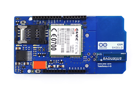
You probably noticed the big orange thing in the GSM shield, this is a 2200uF capacitor (592D228X96R3X2T20H), low ESR and MLCC also, a kind of mini-battery just at the input of the 5V from arduino, I suppose they put this to solve the problem of the low current coming from arduino. I think this is what let me open GSM, register GPRS and do a couple of HTTP POST before everything hangs out, but even with that little orange chocolate bar on top, it had not enough energy to go on.
In the circuit you see that power can come also from Vin pin to the LMZ12002 regulator, so that was my solution. With a 4xAA battery holder everything works fine:
 |
| GSM Shield poewerd with AA batteries |
Here you can see the shield drawing 1.5A at the exact momment of transmission of an HTTP POST.
 |
| GSM Shield drawing 1.5A from 4xAA batteries |
The 4xAA battery holder gives 6V aprox as input, that meets LMZ12002 input range, and is also enough for arduino. In my version (arduino UNO) it uses a 7805 regulator, that has 2V dropout voltage, so atmega is powered with 4V aprox, which it is not a inconvenience, nor for timing:
 |
| ATMEGA328P maximum frequency related to input V |
nor for voltage levels, these are the serial logic level references for Quectel M10:
 |
| Quectel M10 serial interface logic levels |
SoftwareSerial issues
GSM shield uses software serial to connect with arduino thorugh digital pins 2 and 3. In fact, these two pins, and digital 7 for reseting the modem from arduino are the only data connections between both, and that is a good thing, because it lets you almost every arduino pin free to do whatever you want and hardware serial remains free to connect arduino usb and debug while modem is working.
The problem with this is that SoftwareSerial is tricky when used with other libraries that deal with interruptions, it has problems with Servo library for example, and also here with GSM library. GSM3SoftSerial class in GSM library is almost a copy of SoftwareSerial class, and do the same with interruptions, it attachs functions to handle ALL external pin change interrupts PCINT0,1,2 of atmega328p, the same as SoftwareSerial, so if you try to compile a sketch that imports both libraries you will get an error like this because of that duplicity of interrupt vector attachments:
One possible solution to this is to change GSM library to attach interrupts just for the pins 2 and 3, that can be done several ways, these are two of them:
1. Using this very good library arduino-pinchangeint, but you should change all interrupt attachments in your code to use this library, it provides attachInterrupt function on PCINT0,1,2 just as with the built-in arduino attachInterrupt for INT0 and INT1. For example:
2. As digital pins 2 and 3 are in the range of pins of PCINT2 (atmega328p has 3 external pin change interrupts PCINT0,1 and 2, each one for one port, so you have to distinguish inside the function attached which bit generated the interrupt..)
GSM library will work just attaching interrupt function to PCINT2 vector, so you can comment the rest of the attachments on GSM3SoftSerial and comment PCINT2 attachment on SoftwareSerial, like this:
SoftwareSerial.cpp
GSM3SoftSerial.cpp
I have tested and works fine, so with this trick you can mix both libraries in your project and avoid that limitation.
Debug mode
Just define the GSM class as this:
and you will get printed into Serial the AT commands between atmega and the modem, very useful to see what is happening inside, for example I got my SIM locked and I was able to see that the modem was asking for the PUK thanks to this.
Here is the AT command reference, and here a more detailed document about TCP/IP treatment in the modem.
GSM shield uses software serial to connect with arduino thorugh digital pins 2 and 3. In fact, these two pins, and digital 7 for reseting the modem from arduino are the only data connections between both, and that is a good thing, because it lets you almost every arduino pin free to do whatever you want and hardware serial remains free to connect arduino usb and debug while modem is working.
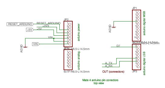 |
| GSM shield connections to arduino |
The problem with this is that SoftwareSerial is tricky when used with other libraries that deal with interruptions, it has problems with Servo library for example, and also here with GSM library. GSM3SoftSerial class in GSM library is almost a copy of SoftwareSerial class, and do the same with interruptions, it attachs functions to handle ALL external pin change interrupts PCINT0,1,2 of atmega328p, the same as SoftwareSerial, so if you try to compile a sketch that imports both libraries you will get an error like this because of that duplicity of interrupt vector attachments:
SoftwareSerial.cpp:312: multiple definition of `__vector_4'The error will be something like that, depending on what library you import first.
GSM3SoftSerial.cpp:521: first defined here
SoftwareSerial.cpp:316: multiple definition of `__vector_5'
GSM3SoftSerial.cpp:525: first defined here
One possible solution to this is to change GSM library to attach interrupts just for the pins 2 and 3, that can be done several ways, these are two of them:
1. Using this very good library arduino-pinchangeint, but you should change all interrupt attachments in your code to use this library, it provides attachInterrupt function on PCINT0,1,2 just as with the built-in arduino attachInterrupt for INT0 and INT1. For example:
PCintPort::attachInterrupt(PIN7, myfunction_pin7int,CHANGE);
PCintPort::attachInterrupt(PIN5, myfunction_pin5int,RISING);
2. As digital pins 2 and 3 are in the range of pins of PCINT2 (atmega328p has 3 external pin change interrupts PCINT0,1 and 2, each one for one port, so you have to distinguish inside the function attached which bit generated the interrupt..)
D0-D7 = PCINT 16-23 = PCINT2 vector
D8-D13 = PCINT 0-5 = PCINT0 vector
A0-A5 (D14-D19) = PCINT 8-13 = PCINT1 vector
GSM library will work just attaching interrupt function to PCINT2 vector, so you can comment the rest of the attachments on GSM3SoftSerial and comment PCINT2 attachment on SoftwareSerial, like this:
SoftwareSerial.cpp
#if defined(PCINT0_vect)
ISR(PCINT0_vect)
{
SoftwareSerial::handle_interrupt();
}
#endif
#if defined(PCINT1_vect)
ISR(PCINT1_vect)
{
SoftwareSerial::handle_interrupt();
}
#endif
/* disable this interrupt to enable them at GSM libray
#if defined(PCINT2_vect)
ISR(PCINT2_vect)
{
SoftwareSerial::handle_interrupt();
}
#endif
*/
GSM3SoftSerial.cpp
/* use just the attachments needed for GSM shield
#if defined(PCINT0_vect)
ISR(PCINT0_vect)
{
GSM3SoftSerial::handle_interrupt();
}
#endif
#if defined(PCINT1_vect)
ISR(PCINT1_vect)
{
GSM3SoftSerial::handle_interrupt();
}
#endif
*/
#if defined(PCINT2_vect)
ISR(PCINT2_vect)
{
GSM3SoftSerial::handle_interrupt();
}
#endif
I have tested and works fine, so with this trick you can mix both libraries in your project and avoid that limitation.
Debug mode
Just define the GSM class as this:
GSM GSMAccess = true;
and you will get printed into Serial the AT commands between atmega and the modem, very useful to see what is happening inside, for example I got my SIM locked and I was able to see that the modem was asking for the PUK thanks to this.
Here is the AT command reference, and here a more detailed document about TCP/IP treatment in the modem.
Client Timeout
Another important parameter to tune, at least in my case where GSM signal was a bit weak, is the Timeout for the GSMClient, by default it is set to 1000ms, but I changed it to 2000ms and thing where better, I stop getting TCP connections closed prematurely.
GSMClient client;
...
...
client.setTimeout(2000); //generic method for Stream class
Hi Carlos.
ResponderEliminarThank you for your technical explanation, it was really interesting.
I have a problem with my GSM Shield, unfortunatelly I don't find anything related on your post.
Can you please take a look on my thread on Arduino forums?
- http://forum.arduino.cc/index.php?topic=183135.0
Thank you!
Hi Carlos, congrats for this excellent post.
ResponderEliminarCould you please add a complete example as how to use the PinChangeInt option? I have been trying to compile using your approach without success. Many thanks in advance.
Hi Simon, you can find some complete examples here: https://code.google.com/p/arduino-pinchangeint/wiki/Usage
EliminarThanks Carlos, I got it running now. Problem still with the fact that is quite unstable. My setup sends an API to Pushingbox every two minutes and after some time working fine (from hors to days) it suddenly stops transmitting. Very frustrating / disappointing.
EliminarYes it was the same in my case, I think the powering to the board is critical, a battery able to provide high busrt currents, perhaps some lipo... what kind of battery are you using?
EliminarHi Carlos, no battery at all, I'm using a 2.5 A 9 Volt power supply. I've even implemented the modem Emergency Pin reset suggestion posted by AndersHedberg on the Arduino forum (http://forum.arduino.cc/index.php?topic=159063.msg1245917#msg1245917) which keeps it working for a longer period but still hangs after some time. I'm considering now to try a 555 based Watch Dog circuit to reset the whole setup every a couple of minutes. Pretty low tech...
Eliminararduino gsm gprs library: http://elecfreaks.com/store/download/datasheet/wireless/GSM_Shield2.zip
ResponderEliminarHi Keven can you elaborate (explain) about your post?
ResponderEliminarThanks, Simon
Thanks, Carlos
ResponderEliminarThis is Gold:)
Do you have any idea why this problem could occur:
ResponderEliminarhttp://forum.arduino.cc/index.php?topic=282519.0
Thanks.
Thank you so much, works great!
ResponderEliminarHi Carlos. It works like a charm on Arduino Uno. But what should you do to make it work on Arduino Mega? Thank you!
ResponderEliminarNice information, thanks for sharing this detailed information i will bookmark this blog for future use.
ResponderEliminarARDUINO AND SHIELD
Dear All,
ResponderEliminarMy gsm M10 + Arduino Mega is not working properly and I do not know what to do. In the beginning it gets stuck when starting the gsmAcess.begin(PIN, true, true). In the debug I only get AT%13%.
Hope you can help me.