I found myself in the situation where I had to stack on top of Arduino two shields that used the same pins for different purposes. It is very probable to happen this to any medium complexity project that requires the functionality of two different shields. In this case I am showing a very simple way I used to solve this problem of incompatibility between GSM shield and Motor shield R3.
It is just a matter of mapping pins from bottom layer shield to the upper one. On the shield you cannot change which pin is connected to which part of the on board circuitry, but there is a chance of changing the Arduino pin that shield pin is connected to..
To illustrate the incompatibility, the schematic of the GSM shield usage of connectors is the following:
 |
| GSM Shield Connectors |
It uses the digital pins D2 and D3 for SoftwareSerial communication between Arduino and the GSM modem. The D3 (marked as number 4 in the figure) is colliding with the D3 on Motor shield, as it is connected to PWMA pin that controls the Enable (% of power to a specific motor) Input of Motor named A on motor shield. Here you can see the connectors:
 |
| Motor Shield R3 connectors |
In this case the solution is easy, as in the GSM shield almost all digital pins are not used, although not every digital serves for the purpose, as what we need is a PWM output, which just can be obtained from timer Output Compare Registers (OC2A, OC2B, etc..) , in the case of atmega328p this corresponds to:
- Timer 2: D11, D3
- Timer 1: D9,D10
- Timer 0: D6,D5
I choose the D5 pin that is the closest one to the original used for PWMA (D3). In fact there are ways of generating a PWM output on any digital pin: you can do it manually or use any software library for generating Software PWM using interrupts, as the Servo library do.
Now it is just a matter of soldering a matching board that will be sandwiched by GSM shield below and Motor shield above.This matching board just connects D5 pin from bottom to D3 above:
 |
| HomeMade Matching board |
 |
| Bottom view |
I used a strip board that I had over here decades ago, it resulted very useful as every connection is made by default (for power connector, etc..), you just have to make a break in the middle (with a cutter o little saw), and then connect the pin from the male connector D5 to the female connector D3, and cut the direct connection from the original D3, to on-top D3 of course.
Here you can see it at work in my internet controlled car:
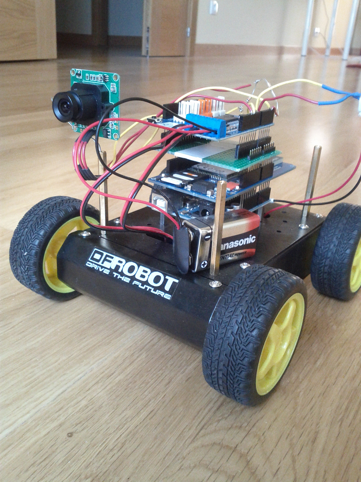 |
| Matching board on car |
As a note, specific to GSM Shield, I tried firstable to place the Motor Shield on top of arduino, and put the GSM shield at other place, connected by wires, as it just would be necessary to connect power pins , D7 for resetting the modem from arduino and D3/D2 for serial communication with the modem. But this idea was not good, I got a lot of strange characters from modem while debugging, erratic hang outs, etc.. it took me a while to realize that the connecting wires from arduino D2/D3 to GSM shield D2/D3 (10 cm long) were acting as antennas and introducing noise, with 2cm wires this did not happen, but that was to short to get anything practical.
No hay comentarios:
Publicar un comentario