domingo, 7 de julio de 2013

Internet controlled Arduino car


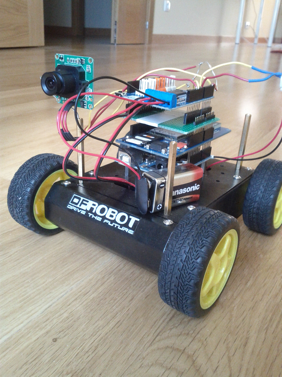
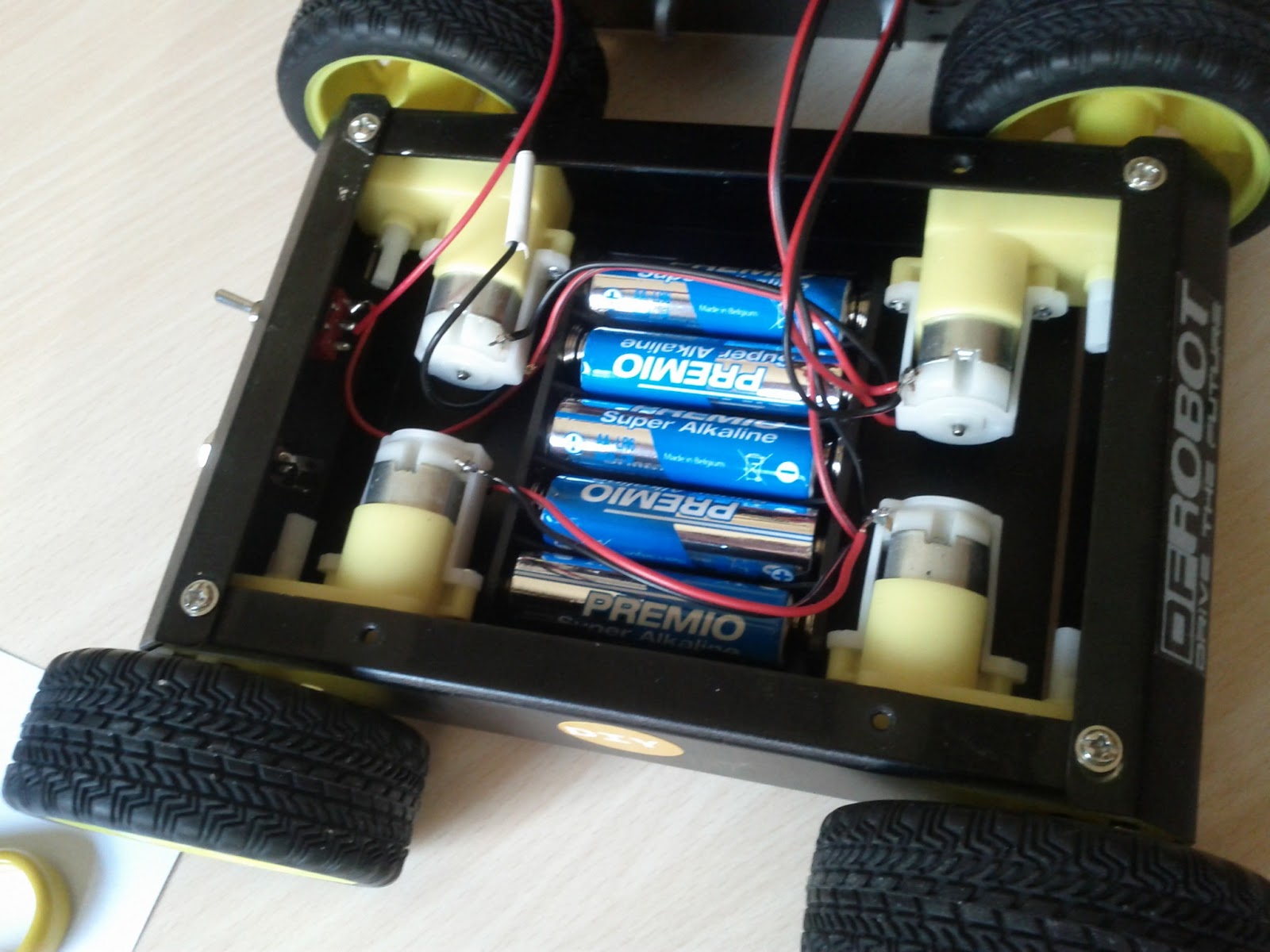
Just to give an idea of the project, firstable I want to show you the end result:


This is a car that can be controlled from a web that acts as a remote control panel where you can send simple movement commands to the car and see the pictures that the attached camera is sending continuously.
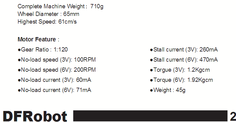
The parts used are:

- TTL Serial VC0706 camera.
- Arduino motor shield R3.
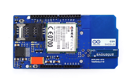
- GSM shield "bluevia".
- Arduino UNO

Probably the best way to control the car from internet is to deploy a web server at the gsm shield and receive commands through it. That is what I tried first, the GSM library has the proper class to do it: GSMServer, and it is well documented and with a couple of examples, but for this to work you need your ISP to allow incoming connections, what was not my case (Orange, in Spain). 

So I decided to set up the control in a server at internet where the car will connect to ask for the commands. The modem in the GSM shield (Quectel M10) has a maximum rate of 85Kbps for GPRS, so it would be good to have the least possible overhead on any TCP/UDP protocol used to make things run as fast as possible and have some acceptable responsiveness. It is also not easy to deploy a tcp server on any free hosting, so I though that the HTTP overhead in the communications would fit enough and as I had to deploy a web page for the remote control panel, a simple ASP page that accept POST calls asking for commands was the final solution. The final architecture of the system is this:

Remote Car Control architecture

The control panel appearance is like this:

Remote car Control Panel

It is a web where you can see the pictures that the car is sendind periodically, and where you can save orders for the car. That orders are simple movements (Forward, Backward, Left, Rigth) and the time you want each order to be executed. This is a very rude way of controlling a car, I know...but think of it as a starting point for controlling some motors from internet and having a view of the effect of that movement.

It uses a free ASP web hosting (SmartASP) and mysql database to store the commands. The picture is stored at the server filesystem and the web updates it continuously using Ajax. Here you can get the whole Visual Studio solution for the server part, the web that takes care of serving the commands and receiving the pictures, and the web frontend.

The algorithm in Arduino is simple (code):

  1. Connect to GSM and start GPRS
  2. Take a picture with the camera
  3. Compose a POST call which sends the picture to the server
  4. Process the POST response, where the command is contained in the form of "movement;time". For example "1;1" means: move forward during 1 second.
  5. GOTO 1


If you want to make this project you will find more information on other posts of this blog about the parts involved on it. This is just a proof of concept, I think both the GSM shield and TTL camera offer a lot of possibilities to improve this system and to do other interesting things, or just to enjoy!.


TTL Camera VC0706 

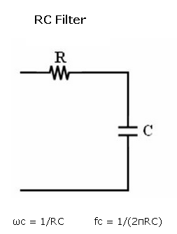
Using the camera is not complicated if you follow the detailed instructions at Adafruit. It is a great camera, just take care of the resistor divider at the reception pin, as Arduino works at 5V and the camera at 3.3V TTL. It has three resolutions, I used the smallest one (160x120) that results in a photo of about 3Kbytes. One tricky thing is that you have to put a little delay after the begin() of the serial connection to the camera, before taking the picture.

The camera can detect motion, that opens the door for a lot of interestings projects...


Here you have a video of the whole system working:


domingo, 30 de junio de 2013

RAM issues in Arduino atmega328p


It wasn't until I needed to use a GSM modem together with a microSD until I realized the RAM limitations on atmega328p micro. It made me learn some interesting things about RAM saving techniques on Arduino and how to deal with SD cards. 

The project was about sending some data stored in a microSD card to a internet site using GSM Shield, but concepts learned can be applied to any RAM limited project, or any project dealing with SD cards, beacuse as I have seen in forums, these RAM problems happen to many people at the time of including a SD to a project.


atmega328p RAM 

You probably have read this in the atmega328p datasheet:

  • 4/8/16/32K Bytes of In-System Self-Programmable Flash progam memory (ATmega48PA/88PA/168PA/328P)
  • 256/512/512/1K Bytes EEPROM (ATmega48PA/88PA/168PA/328P)
  • 512/1K/1K/2K Bytes Internal SRAM (ATmega48PA/88PA/168PA/328P)

I had, but didn't take much care about it because my sketches (+ 512 bytes of the optiboot bootloader) were less than that 32KBytes (32768 bytes).

From the atmega datasheet, the RAM memory map is this:

atmega329p RAM memory map

so we have 2048 bytes for the executing program.


How to detect RAM problems


In my case: in the Serial.print debugging messages began to appear strange things, and I could recognize part of texts from others lines in the code merged with the expected ones plus some strange characters. It seemed like the program was accessing an incorrect part of the RAM or that those bytes in the  RAM were overwritten. In general when you run out of RFAM you can expect any abnormal behaviour from your program, even it need not to be at the startup. The program will upload without problem, you can run out of RAM at any

If you have doubts, use this popular function to get the current available free RAM:

int freeRam () {

  extern int __heap_start, *__brkval;

  int v;
  return (int) &v - (__brkval == 0 ? (int) &__heap_start : (int) __brkval);
}
__heap_start is a avr-libc variable that the linker automatically set to the heap start section, and that malloc uses to know where to start to use memory (char *__malloc_heap_start = &__heap_start;), __brkval is a variable that stores the highest point used in the heap.


RAM saving techniques

There is a lot of information and advices about techniques for saving RAM, but the principal findings for me were:

  • Strings in C are copied to RAM, to store them in Flash use the F() macro inside functions and/or PROGMEM attribute. Quite interesting  how F() manages to access Flash data address space (remember it is Harvard arquitecture, data and program memory are separated)
  • If there is a communication buffer in your library be aware of its size, specially for SD libraries as they need exactly 512bytes (data block). Other libraries like HardwareSerial automatically fit the buffer size depending on free RAM:
#if (RAMEND < 1000) 
#define SERIAL_BUFFER_SIZE 16
#else  #define SERIAL_BUFFER_SIZE 64
#endif
          • If you really need String class.., use reserve() function, it is much better to reserve the exact size from the beginning (detailed explanation here)


          microSD libraries

          It was when I included the Arduino Sd library (#include <SD.h>) when my problems began, it was too much for atmega running GSM library and SD, beside lots of then unconscious Serial.print("blablabla")...


          After some investigation you realize that there are several SD library implementations out there, and Arduino IDE default one is not the best for optimizig RAM. The best I found was SDFat library. It comes with lot of examples, includes benchmarking sketches to compare to standard SD library performance, and also contains a MiniSerial class to substitute Serial, after changing to SDFat and massive use of F() macro all my RAM problems became solved. Hope this helps!

          I leave here my code, it sends a complete file using GPRS to a web site using POST.

          It can also help thie reading on optimizing c code for avr:

          Tips and Tricks to Optimize Your C Code for 8-bit AVR Microcontrollers 


          Solving pin incompatibility between arduino shields


          I found myself in the situation where I had to stack on top of Arduino two shields that used the same pins for different purposes. It is very probable to happen this to any medium complexity project that requires the functionality of two different shields. In this case I am showing a very simple way I used to solve this problem of incompatibility between GSM shield and Motor shield R3.

          It is just a matter of mapping pins from bottom layer shield to the upper one. On the shield you cannot change which pin is connected to which part of the on board circuitry, but there is a chance of changing the Arduino pin that shield pin is connected to..

          To illustrate the incompatibility, the schematic of the GSM shield usage of connectors is the following:

          GSM Shield Connectors

          It uses the digital pins D2 and D3 for SoftwareSerial communication between Arduino and the GSM modem. The D3 (marked as number 4 in the figure) is colliding with the D3 on Motor shield, as it is connected to PWMA pin that controls the Enable (% of power to a specific motor) Input of Motor named A on motor shield. Here you can see the connectors:

          Motor Shield R3 connectors

          In this case the solution is easy, as in the GSM shield almost all digital pins are not used, although not every digital serves for the purpose, as what we need is a PWM output, which just can be obtained from timer Output Compare Registers (OC2A, OC2B, etc..) , in the case of atmega328p this corresponds to:

          •  Timer 2: D11, D3
          •  Timer 1: D9,D10
          •  Timer 0: D6,D5


          I choose the D5 pin that is the closest one to the original used for PWMA (D3). In fact there are ways of generating a PWM output on any digital pin: you can do it manually or use any software library for generating Software PWM using interrupts, as the Servo library do.

          Now it is just a matter of soldering a matching board that will be sandwiched by GSM shield below and Motor shield above.This matching board just connects D5 pin from bottom to D3 above:

          HomeMade Matching board
          Bottom view

          I used a strip board that I had over here decades ago, it resulted very useful as every connection is made by default (for power connector, etc..), you just have to make a break in the middle (with a cutter o little saw), and then connect the pin from the male connector D5 to the female connector D3, and cut the direct connection from the original D3, to on-top D3 of course.

          Here you can see it at work in my internet controlled car:

          Matching board on car


          As a note, specific to GSM Shield, I tried firstable to place the Motor Shield on top of arduino, and put the GSM shield at other place, connected by wires, as it just would be necessary to connect power pins , D7 for resetting the modem from arduino and D3/D2 for serial communication with the modem. But this idea was not good, I got a lot of strange characters from modem while debugging, erratic hang outs, etc.. it took me a while to realize that the connecting wires from arduino D2/D3 to GSM shield D2/D3 (10 cm long) were acting as antennas and introducing noise, with 2cm wires this did not happen, but that was to short to get anything practical.


          martes, 25 de junio de 2013

          Arduino GSM Shield tips & tricks


          There are a lot of ways you can use a shield like this to improve your projects. I purchased it with the aim of mounting it into a rc car and controlling it from internet, including some video transmission to make a kind of remote car control panel, challenging project for me..., but that will worth another complete post, here I am focusing on GSM Shield.

          I had never used a GSM shield and through the process of setting it up and testing I found some tips that I think that could be useful to other people facing this GSM Shield for the first time.


          Power issues

          This is a critical point, with almost every GSM shield a far as I could read. If you get erratic errors, your modem hangs out or your code stops forerever and you are powering it from USB then you are lucky because there are a lot of chances that all these problems will become solved when you change to another power source that is not limited to 500mA. 

          In the Quectel M10 datasheet there are interesting comments about powering the modem: input voltage is between 3.4V and 4.5V, and current drawn can grow up to 2A at transmission bursts, causing voltage drops. A 100uF low ESR (Electrical Series Resistance) capacitor is recommended as near as possible to VBAT pin of the modem, MLCC (multilayer ceramic chip) capacitors are said to meet this low ESR and capacity requirements.

          In this shield the powering circuit is the following (shield schematic):

          GSM Shield powering circuit with LMZ12002 switching regulator

          The circuit is based on the LMZ12002 switching regulator, which meets the requirements:
          • Up to 2A Output Current
          • Input Voltage Range 4.5V to 20V
          • Output Voltage Range 0.8V to 6V
          • Efficiency up to 92%

          We see that the 100uF capacitor (C3225X5R0J107M) is placed near the output VBAT, it is MLCC and low ESR, with a 100nF in paralell, exactly as stated in Quectel datasheet. I though it could work, even powering just from USB (Vin not connected, 5V input to GSM shield is connected to Arduino 5V), with 500mA max current, but it didn't, it starts ok, registers in GSM and starts GPRS connection correctly, but after one or two TCP connections the modem hangs out and even the Serial connection from the arduino die (perhaps because the problem occurs at transmission, when more current is drawn, and before transmitting the interrupts of arduino are disabled with a cli() call in the SoftwareSerial library).

          You probably noticed the big orange thing in the GSM shield, this is a 2200uF capacitor (592D228X96R3X2T20H), low ESR and MLCC also, a kind of mini-battery just at the input of the 5V from arduino, I suppose they put this to solve the problem of the low current coming from arduino. I think this is what let me open GSM, register GPRS and do a couple of HTTP POST before everything hangs out, but even with that little orange chocolate bar on top, it had not enough energy to go on.

          In the circuit you see that power can come also from Vin pin to the LMZ12002 regulator, so that was my solution. With a 4xAA battery holder everything works fine:

          GSM Shield poewerd with AA batteries

          Here you can see the shield drawing 1.5A at the exact momment of transmission of an HTTP POST.
          GSM Shield drawing 1.5A from 4xAA batteries

          The 4xAA battery holder gives 6V aprox as input, that meets LMZ12002 input range, and is also enough for arduino. In my version (arduino UNO) it uses a 7805 regulator, that has 2V dropout voltage, so atmega is powered with 4V aprox, which it is not a inconvenience, nor for timing:

          ATMEGA328P maximum frequency related to input V

          nor for voltage levels, these are the serial logic level references for Quectel M10:

          Quectel M10 serial interface logic levels


          SoftwareSerial issues

          GSM shield uses software serial to connect with arduino thorugh digital pins 2 and 3. In fact, these two pins, and digital 7 for reseting the modem from arduino are the only data connections between both, and that is a good thing, because it lets you almost every arduino pin free to do whatever you want and hardware serial remains free to connect arduino usb and debug while modem is working.
          GSM shield connections to arduino

          The problem with this is that SoftwareSerial is tricky when used with other libraries that deal with interruptions, it has problems with Servo library for example, and also here with GSM library. GSM3SoftSerial class in GSM library is almost a copy of SoftwareSerial class, and do the same with interruptions, it attachs functions to handle ALL external pin change interrupts PCINT0,1,2 of atmega328p, the same as SoftwareSerial, so if you try to compile a sketch that imports both libraries you will get an error like this because of that duplicity of interrupt vector attachments:

          SoftwareSerial.cpp:312: multiple definition of `__vector_4'
          GSM3SoftSerial.cpp:521: first defined here
          SoftwareSerial.cpp:316: multiple definition of `__vector_5'
          GSM3SoftSerial.cpp:525: first defined here
          The error will be something like that, depending on what library you import first.

          One possible solution to this is to change GSM library to attach interrupts just for the pins 2 and 3, that can be done several ways, these are two of them:

          1. Using this very good library arduino-pinchangeint, but you should change all interrupt attachments in your code to use this library, it provides attachInterrupt function on PCINT0,1,2 just as with the built-in arduino attachInterrupt for INT0 and INT1. For example:
          PCintPort::attachInterrupt(PIN7, myfunction_pin7int,CHANGE);
          PCintPort::attachInterrupt(PIN5, myfunction_pin5int,RISING); 

          2. As digital pins 2 and 3 are in the range of pins of PCINT2 (atmega328p has 3 external pin change interrupts PCINT0,1 and 2, each one for one port, so you have to distinguish inside the function attached which bit generated the interrupt..)

           D0-D7 = PCINT 16-23 = PCINT2 vector
           D8-D13 = PCINT 0-5 = PCINT0 vector
           A0-A5 (D14-D19) = PCINT 8-13 = PCINT1 vector

          GSM library will work just attaching interrupt function to PCINT2 vector, so you can comment the rest of the attachments on GSM3SoftSerial  and comment PCINT2 attachment on SoftwareSerial, like this:

          SoftwareSerial.cpp
          #if defined(PCINT0_vect)
          ISR(PCINT0_vect)
          {
            SoftwareSerial::handle_interrupt();
          }
          #endif
          #if defined(PCINT1_vect)
          ISR(PCINT1_vect)
          {
            SoftwareSerial::handle_interrupt();
          }
          #endif
          /* disable this interrupt to enable them at GSM libray
          #if defined(PCINT2_vect)
          ISR(PCINT2_vect)
          {
            SoftwareSerial::handle_interrupt();
          }
          #endif
          */

          GSM3SoftSerial.cpp
          /* use just the attachments needed for GSM shield
          #if defined(PCINT0_vect)
          ISR(PCINT0_vect)
          {
            GSM3SoftSerial::handle_interrupt();
          }
          #endif
          #if defined(PCINT1_vect)
          ISR(PCINT1_vect)
          {
            GSM3SoftSerial::handle_interrupt();
          }
          #endif
          */
          #if defined(PCINT2_vect)
          ISR(PCINT2_vect)
          {
            GSM3SoftSerial::handle_interrupt();
          }
          #endif

          I have tested and works fine, so with this trick you can mix both libraries in your project and avoid that limitation.


          Debug mode

          Just define the GSM class as this:

          GSM GSMAccess = true;

          and you will get printed into Serial the AT commands between atmega and the modem, very useful to see what is happening inside, for example I got my SIM locked and I was able to see that the modem was asking for the PUK thanks to this.

          Here is the AT command reference, and here a more detailed document about TCP/IP treatment in the modem.


          Client Timeout

          Another important parameter to tune, at least in my case where GSM signal was a bit weak, is the Timeout for the GSMClient, by default it is set to 1000ms, but I changed it to 2000ms and thing where better, I stop getting TCP connections closed prematurely.


          GSMClient client;
          ...
          ...
          client.setTimeout(2000); //generic method for Stream class

          sábado, 27 de abril de 2013

          Using adafruit motor shield for DC motor & Servos


          In this post I am writting about my experience with Adafruit motor shield. This shield comes unsoldered, so first step is to solder it, for what there is a detailed explanation at ladyada web. In the same web there are code examples to use it for steppers and dc motors, and it is quite simple to use so I am not repeating it here.

          I was interested in experimenting with L293D chip, compared to L298 that I have already used for the same motors (the dc motors of pirate4wd hobby car). The final purpose is to have an rc car controlled by arduino gsm bluevia shield. The results of this tests will make me decide to use L293D or L298. I can tell you right now the result: I am using adafruit motor shield (L293D) instead of arduino motor shield (L298). This is just beacuse it works better for this dc motors and with the battery I use, of course it cannot be deduced that one is better than the other in every situation.


          Things that can be learned in this project:

          - L293D motor driver and batteries
          - Shift Register (74HCT595, the chip in the middle of the shield)
          - Servo Motors: fascinating Servo library and tips about how to supply power to them.


          L293D & batteries

          Quadruple half H Brigge, same as double full bridge of L298. L298D has output clamp diodes incorporated (not in L298), and ouput current 600mA (1.2A peak) per channel, compared to the 2A per channel of L298, that are the most important differences. 

          Remembering the current consumed by the dc motors of pirate4wd car, and taking into account that motors are paired, I will need maximum 260mA per motor (520mA total as they are parallel connected) for 3V operation, and aproximately double of that for 6V operation. I couldn't find the saturation voltages for L298D in order to calculate the voltage that will rest for dc motor from motor supply, but multimeter reads about 2V between motor + and -, both for 9V battery and 4xAA battery (6V), so it should be similar to L298, between 3V and 6V.


          I tried two powering options:

          - 9V battery, this batteries are not known for offering great current drain. In datasheet you can see that they are designed for moderate and medium drain devices (not for toys for example). The reason of this is that this batteries are composed of several small cells in series, small cells with few mAh capacity  (200mAh) , and draining for example 500mA will make voltage drop rapidly.

          - 4xAA battreries, 6V total,  less voltage for motor, but greater current response, dc motors run better. The capacity of each AA is between 1500mAh and 3000mAh, that will respond better to a "high" current drain of 500mA. 


          Anyway, it was a good opportunity to read and learn about batteries, I recommend this post from letsmakerobots, and reading a couple of battery datasheets, one interesting point is that battery capacity (mAh) depends a lot on the drained current in the case of alkalines, and not so much for lithium ones. For a 9V alkaline battery, with a 500mA load, battery capacity is about 400mAh, and with a 25mA load it changes to 600mAh. Another point is that not all batteries offer high currents so happily, each one is designed for a type of load, and that is something to take into account when choosing one for your motor.


          74HCT595 Shift Register

          Actually I made it work without knowing this chip internals, just that it was used to get 8 digital outputs from 4, so the only purpose of it is to save 4 arduino digital outputs to use 2 of them with servos, and even leave a couple of arduino digital pins free (2 and 13). Each L293D uses 4 input pins plus 2 enable controls, a total of 6, which means 12 digital outputs for 4 motors, the total of available digital pins on arduino (0-13, but 0 and 1 are serial rx and tx).

          Trying to understand the board completely I searched and found this excellent deep explanation at the ladyada faqs page for this shield, it is a very interesting document for beginners such as I. Although explains it based on an old AFMotor library code that used atmega ports to manage 74HCT595 inputs, the new version of this library uses arduino pins directly and digitalWrite on them instead of dealing with atmega ports B and D registers (DDRB, PORTB).


          Servo motors & Servo Library

          If you don't know how a servo works, you can read this simple introduction, or search the internet, there is a lot of info out there about it. Knowing that, servo library usage is simple and well documented, what seemed fascinating to me is the complexity of its internal management of timers to generate PWM.

          The basic principle is to use atmega timers to trigger interrupts every 20ms and generate the needed pulse width at digital outputs, not so complicated, but Servo library says that can manage up to 12 servos, and atmega328p just have 3 timers, and timer0 is used for timing functions that are still available when using Servo library. Depending on the platform, the library uses a predefined set of timers, and in the case of atmega328p, it uses just Timer1 (16bits), and the cost is that we can't use PWM (analogWrite) on digital pins 9 and 10. This is because these are the arduino pins that corresponds to Output Compare Match OC1A and OC1B of Timer 1.

          The way the library maps ticks to real time is using these functions located at Arduino.h:

          #define clockCyclesPerMicrosecond() ( F_CPU / 1000000L )
          #define microsecondsToClockCycles(a) ((a)*clockCyclesPerMicrosecond()) 

          that takes into account the real cpu clock configured for the micro. 

          One thing I didn't understand completely is why 12 servos, servo signals can last from 1 to 2ms, suppose the worst case: all 12 servos are set to 2ms, that sums 24ms, and servo protocol expects a signal every 20ms (50Hz). Investigating the code and servo protocol you can see that, in that case the next interrupt will began just after last servo is served, so the frame rate will decrease that cycle to 41.6Hz, a drop of 16%, decreasing the frame rate means that servos will reduce holding power, speed and precission. Servo library uses REFRESH_INTERVAL constant (set to 20ms) to ensure the maximum frame rate, but doesn't control the minimum, just controls the number of servos per timer, what yields to 41,6Hz in the worst case, I suppose that is the maximum deviation assumed, and why the maximum number of servos is set to 12.

          One important point for using servos is how to power them. In the adafruit board, servo power comes from arduino 5V (no easy way of powering from motor power inputs), and this is not adequate for my microservos. Every time I move servos arduino resets itself, I suppose beacause of a lack of power that makes brown-out detector to auto reset. In arduino UNO (atmega328p) the Extended Fuse default is set to 0x05, which sets the BODLEVEL to 2.7V, so I suppose servo drains so much current that triggers arduino Brown-Out Detector. Here is a detailed explanation of why servos should be powered from a different source that arduino.

          This happens with arduino powered from USB 2.0 (500mA max load), but if I powered arduino from a wall adapter there is no problem as it drains more than 500mA (1000mA exactly, at 12V).

          At the end, as I needed to power the servo in the rc car,  I used one battery for arduino and another one for dc motors and servos (4xAA) connected through the ground pin to the arduino GND. I think it is a bit forced, 6V is too low for dc motors, but microservo voltage range is [4.8-6]V (datasheet), the other option was to use 3 batteries...

          There is a curious conflict using Servo and SoftwareSerial libraries together that drove me mad some days. I used SoftwareSerial to access the xbee shield. The first times, once I connected the remote control and it began to send i/o samples to the xbee in the car, the servos began to move erraticaly, I though it was some kind of problem involving batteries, evil spirits and xbee draining too much at transmission time. At the end I discovered it was a software problem, beacuse the SoftwareSerial library disable interrupts when transmitting (cli();), and that interferes with the Servo library way of generating "pwm" signal, you can see here a video showing the same problem in another project. I avoided to solve the software problem and directly used Serial communication for xbee shield, but it could be a challenging project to make both libraries to live together in peace.

          By the way, the servo will be used to move a platform that holds a camera that will be controlled wirelessly through the gsm shield, but that will be another day.

          My code for the arduino at the car.

          domingo, 21 de abril de 2013

          Arduino Motor Shield R3


          I purchased an arduino motor shield to use it with the pirate4wd car chasis, but at the end I was able to design my own board (previous post) including atmega328p and L298 circuit. So just for justifying the money spent I wanted to try it, and here I show what came out of that test.


          Firstsable I was a bit dissapointed with the board, with 6 output connectors I thought I could control lots of things, perhaps both dc motors and servos, but:

          - outputs TWI IN and TWI OUT were unusable, as I had an Arduino UNO R2, and this board is designed  for Arduino UNO R3, which has a couple of extra connectors on each side. Two of them are SDA and SCL, used for TWI connectors. Apart from that, you can use it with Arduino UNO R2 without problems.

          - outputs OUT 5 and OUT 6 (Orange ones), connected to two arduino digital pins, are powered with 5V from arduino, and I expected them to be powered from motor shield Vin, to separate motor power from arduino and avoiding unstabilities on Arduino. If don't know why you can read this excellent web. Anyway 5V from Arduino could be enough for small hobby servos..


          That's the bad part, the rest went quite as expected. First thing was to cut Vin connect jumper that connects shield power and arduino power (just cut the small connection with a cutter or little screwdriver)

          I could use the same code as with my homemade board, just changing inputs and pwm pins adequated to the motor shield pins and considering that IN2 is IN1 inverted if brake jumper is connected (and IN4 is IN3 inverted).


          One interesting thing I found useful was the treatment of sense signals, with and opamp to set up the range [0-3.3V] (been 3.3V max current: 2A), and impedance to arduino ADC inputs.


          I had some measurements to test the current drawn by the motors in several conditions

          Car hold on air. There are two motors connected in parallel, so supposing half of the current for each, at the beginning it sources 450mA and after that it reduce to 300mA average


          Car fixed, no movement (Stall current). Much more that on air as expected, motor 600mA per motor at the very first and 500mA after first spike. But 1200mA total, not reaching the 2A limit of L298 but justifying using one channel for two motors, other option coould be a couple of L293, one for each two motors as it has 600mA per channel, and a peak current of 1200mA (it can be interesting to test forcing one L293 for the two motors)


          Car free running on floor. First spike simillar to stall current: 600mA per motor, but after that it decays to 250mA per motor. That first spike is on of the reasons why motor power should be separated from microcontroller supply.


          Finally a photo of the car using the motor shield.


          martes, 16 de abril de 2013

          Arduino rc car using L298 and Xbee S1


          I will share here my first experience making something that moves. Is a simple rc car made with dfrobot pirate4wd chasis platform, a homemade arduino using atmega328p, LM298 as motor driver and a couple of xbee s1 to remotely control it.


          I learned interesting things with this project, useful things that can be (will be) used in another projects that involves controlling motors remotely, that things are:

          - xbee i/o line passing as a very simple way of communicating sensor data.
          - motor drivers, considerations on power, types of motors, get introduced to it at least


          The remote control


          It is composed of a parallax joystick, a Xbee Explorer Regulated and a Xbee S1, all powered thorugh a 3.7V Lipo. The Xbee Explorer Regulated has a Micrel 5205 regulator, very low dropout (150mV at 45mA, that is the transmit current of Xbee S1), so 3.7V supply is ok.

           I got inspired at this web, Digi Xbee modules have an interesting thing that is I/O line passing, which consists in sending wirelesly analog and digital signals connected to certain pins, it is well explained at Digi site both for analog and digital. Internal ADC is 10 bits, enough for passing parallax joystick values.


          It is easier in S1 modules, as you have external VREF for ADC, in S2 VREF is internally referenced to 1.2V, so you will have to accomodate analog signal to that range. I did it with Xbee S1, connecting VCC to VREF (pin 14, named RES in Xbee Explorer Regulated), and to the joysctick VCC, it is easier and need less components.


          If you want to do it with Xbee S2 you will need a voltage divider, and if not familiar with it, this reading will be useful, as you will have to consider Xbee ADC input impedance (1Mohm for series 2) and voltage source output impedance (for my joystick, with a 4K7, beeing in the middle will be 2k3 using Thevenin theorem, in the order of Kohms anyway. Resistor values should be bigger than voltage source output impedance and smaller than adc input impedance, something in the order of 100kohm will be good.

          So, connecting joystick outputs to analog inputs of Xbee, select from joystick to digital input, configuring it as indicated in the link above, you will have the values at the receiver, in series 1 (802.15.4) you can get the values atthe receiver both through the UART (setting IU=1), and/or as PWM outputs. Depending on your purposes, you can use directly the PWM, but remember, is not "real" analog, you must use a RC filter to get the analog DC, also explained at digi.


          In my case I recieved the API packet (line passing needs API mode), and get the values in my arduino/atmega328p code to process them and make the pirate4wd move according to joystick.


          The car

          The chasis used is the pirate4wd from dfrobot, mine came without manual, but it can be found online, although it is not really necessary, just to know the dc motor characteristics:


          Seen the stall current perhaps a L298 is oversized, as it can source up to 2A per channel, but I just wanted to test this chip, I will have another try witrh L293 soon.
          The controller is constructed at a pinhole board with atmega328p at 16Mhz, xbee socket for receiver mounted on Xbee Regulated board, 7805 5V regulator for atmega and L298 with its army of diodes (1N0007).


          First thing is to solder motor cables, as L298 only has outputs for two motors, one solution is to connect each side motors to the same cable, but with polarity inverted, as they are oriented in opposite directions. Solder interruptor from batteries holder and then to a power output to the control board.


          After mechanical part is solved, you have to deal with L298 control with atmega, you can find lot of tutorials online. If you don't already know, it is a good opportunity to learn about H brigde motor controllers. Knowing that, you just have to control motor direction with IN pins, and motor power level with ENABLE pins, using a PWM atmega output. I leave here my code.


          Some tips that could be useful for other people trying to do something similar:

          - socket for L298, as pins are separated 0.05 inch, you cannot connect it directly to a 0.1 inch hole board, it can be solved bending 45º the legs of a pin strip, solder that to the board and inserting L298 on it.
          - separate power to motors and to microcontroller, I tried firstable powering 7805 5V output to atmega328p and regulator input to Vs pin of L298 (and output diodes supply) and I could see the current breakdown when driving the motor through a "power on" led connected an atmega digital ouput. After powering motors with a separate 9V supply, there is no influence from motors to microcontroller. Excellent explanation and video here.
          - consider 9V min battery for motors. The AA batteries holder that comes with pirate4wd is 7.5V, and this is not too much for these dc motors. They will work, but not at 100% of their capacity. They run 100rpm at 3V and 200rpm at 6V, but. even with 7.5V you will have about 2.5V final voltage applied to motors. There is a important characteristic at L298 datasheet, it is the Source and Sink saturation voltage, that sums between 3.2V and 4.9V, so that leaves just (7.5 - 4.9) = 2.6V in the worst case for the motors.


          - consider to program some "throttle smooth start control" in your atmega software, if you drive motor from 0 to 100 in 1 second then probably L298 will saturate (sure if you use less than 9V motor supply), you can see an example of gradual acceleration in my code defining a maximum acceleration per second "MAX_ACELERATION".


          domingo, 14 de abril de 2013

          Playing with sound: wtv020sd & LM386


          I must say I thought managing sound electronically was simpler than it actually is. Interferences, amplifier distortion, impedance matching, it is not easy to get acceptable quality without knowledge about amplification and speakers, so I didn't get it as good as I expected at the beginning, but learned some things that I am going to share, so you could reach some point better than mine.

          The central part of the project was the wtv020sd module from sparkfun.


          It is quite easy to manage with this library. You just have to consider this tips:

          - Chip works at 3.3V, although some people is using it directly with arduino/atmega digital lines at 5V without problems.. The board from sparkfun comes with a 5V to 3.3V regulator, so there is no problem with the supply, but I prefer to shift digital lines level from atmega using a diode and a resistor, as recommended in tip #10 of this great document from Microchip ( I used a 3k3 resistor as recommended in the forum by ac2013)
          - Micro SD standard also works at 3.3V, and it seems that this is the most delicate part, and depending on the SD card the module will work or will not at 5V.
          - Take into account the manufacturer recommendations about audio format (ad4, samples here)
          - Don't take into account the manufacturer recommendation about SD size limit 1GB, I am using it with a 2GB SD card, formated with FAT (not FAT32).
          - The library works good, but you should add a delay in playVoice function, as it reads the busy pin to detect the song's end. 50ms before reading busy pin is enough


          The module has two kind of outputs, one PWM to directly connect a speaker , and one 16 bit DAC to connect to an amplifier. The speaker output works perfect, and quite loud, with a 8 ohm speaker. But if you want it  louder you can use an amplifier stage, you have the circuit for LM386 in the manufacturer datasheet:


          This is how I built it:


          And here is where I reach my limits. I couldn't get a clear sound after the amplifier stage. Even keeping input lines as short as possible, and using all recommended capacitors, with exact values and including 10nF at pin 7 not shown in schematic but useful as I have checked by myself in other audio project, it is used to get 50dB of PSRR = Power Supply Rejection Ratio and it really improves results.


          Amplification works quite fine using low values of 10K input potentiometer that regulates volume, but when I increase volume distortion appears. I must say that using LM386 N1  (325mW output power) it works fine even with high volume, but using LM386 N4 (1000mW output power) distortion appears with low volume.

          I found this graph in the datasheet,


          it relates distortion with output power, for 6V and 8ohm load at 1Khz, and that is exactly what I get, and that are my conditions on load and supply, I get distortion just when the output power is about a 10/20% of maximum (200mW) . So perhaps, if I increase supply and also increase load impedance, I could get same power with less distortion. Let's calculate:

          Suppose P1 = V1*I1 = V1*V1/R1, is the power I have now, with 6V supply and 8ohm load

          If  I double  voltage (12V) and quadruplicate load (32ohm) :V2= 2V1, and R2=4R1, then P2 = 4V1*V1/4R1= P1, and I2 = 0.5I1, I get the same output power but half output current, so probably less distortion (move the curve in the graph to the right), and that matches with the datasheet that says that 1W power can be obtained with 16V, and 32ohm load..But I don't know if all this reasoning is acceptable, I will apreciate comments, for example output voltage is not linear with input supply, that quits precision to my calculation but not quits all the reason.


          Using 9V to supply LM386 I got better results in fact, I could move the potentiometer on the input pin almost to 30% or 40% without distortion. I also measured the input voltage from wtv020sd, that was 1,72V mean, quite high, amplified by a gain of 20 would be more than 30V, which is much more than the supply (= distortion). The maximum gain without distortion would be 9/1.7= 5, that's input pot to 25%.


          Electret, Xbee 868 pro and Cosm graphs


          The pupose of this project is to take noise measurements from a electret microphone, read them with atmega328p ADC and send through xbee 868 pro to a computer where a dongle with another xbee 868 receives the values and send to cosm for showing a graph.

          I will detail here the tips dealing with xbee and cosm, you can read about taking the electret output in a previous post.

          I used xbee 868 pro just because is what I have in hand. Atmega328p is powered at 5V, from a 7805 regulator, so I used a xbee regulated explorer board from sparkfun to connect the xbee. It has a micrel 5205 voltage regulator to suply 3.3V to xbee, and a tricky diode at DIN pin to convert signal lines from 5V to 3.3V.


          This diode is worth some comments, as it gave me some headache, and made me learn some things about pull up resistors, and how they are used for example for I2C bus. I recommend this reading about it:

          Atmega328p output pins are [4.2 - 5]V (5V supply), so, [3.2 - 4V] (diode 1V forward) after DIN diode at Xbee DIN input. And Xbee inputs are [0.8VCC - VCC], that is [2.64-3.3] (3.3V supply). That is supposed to match, but reality is that it is mandatory to have xbee internal pull up at DIN pin activated for this to work. DIN pull up is not activated by default at 868 pro module, you need to activate it with the PR AT command. Don't know what is the exact reason of this not working without it.

          Another tip about using Xbee with atmega328p is about the xbee-arduino library. I had some confusion with API mode, You can configure API mode with AT commands (or X-CTU software), setting AP parameter to 1 (API mode) or 2 (API mode with escaped characters). And after that, everything you send through xbee serial uart will be encapsulated in an API message, so you won't need to create a API message using xbee-arduino library, or you will end up with a complete API message encapsulated inside another xbee api message, but probably you will not be a fool such as I... Rest of the Xbee configuration, destination address broadcast, same net id on both xbee modules, 38400 baud rate (for some reason I had problems using 9600).

          This is a photo of the board that take electret values, amplifies them with LM386 N1 and send wirelessly though xbee:


          In the recepction part I have a small pc, with a xbee usb dongle. It has a c# program that manually parse xbee API message and send the value to Cosm. Here you have the atmega and c# solution. I use SoftwareSerial to connect to Xbee beacuse "standard" tx and rx pins of atmega are used to program the micro and debugging through serial monitor. The important part about sending values to Cosm is this:


          byte[] postArray = Encoding.ASCII.GetBytes(value.ToString());
          WebClient wc = new WebClient();
          wc.Headers.Add("X-PachubeApiKey", apiKey);
          byte[] response = wc.UploadData("http://www.pachube.com/api/" + feedId + ".csv", "PUT", postArray);


          And here you can see the graph obtained at Cosm: