domingo, 30 de junio de 2013

RAM issues in Arduino atmega328p


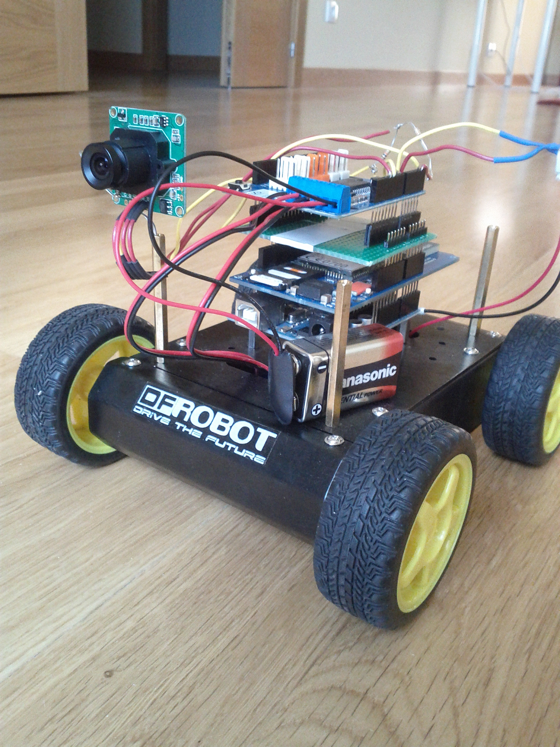
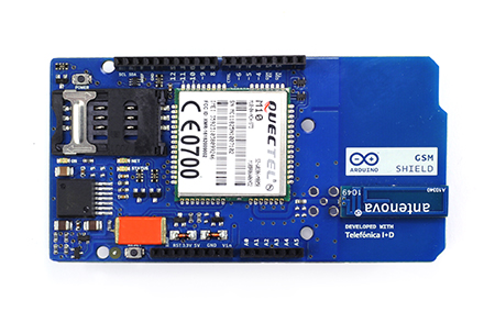
It wasn't until I needed to use a GSM modem together with a microSD until I realized the RAM limitations on atmega328p micro. It made me learn some interesting things about RAM saving techniques on Arduino and how to deal with SD cards. 

The project was about sending some data stored in a microSD card to a internet site using GSM Shield, but concepts learned can be applied to any RAM limited project, or any project dealing with SD cards, beacuse as I have seen in forums, these RAM problems happen to many people at the time of including a SD to a project.


atmega328p RAM 

You probably have read this in the atmega328p datasheet:

  • 4/8/16/32K Bytes of In-System Self-Programmable Flash progam memory (ATmega48PA/88PA/168PA/328P)
  • 256/512/512/1K Bytes EEPROM (ATmega48PA/88PA/168PA/328P)
  • 512/1K/1K/2K Bytes Internal SRAM (ATmega48PA/88PA/168PA/328P)

I had, but didn't take much care about it because my sketches (+ 512 bytes of the optiboot bootloader) were less than that 32KBytes (32768 bytes).

From the atmega datasheet, the RAM memory map is this:

atmega329p RAM memory map

so we have 2048 bytes for the executing program.


How to detect RAM problems


In my case: in the Serial.print debugging messages began to appear strange things, and I could recognize part of texts from others lines in the code merged with the expected ones plus some strange characters. It seemed like the program was accessing an incorrect part of the RAM or that those bytes in the  RAM were overwritten. In general when you run out of RFAM you can expect any abnormal behaviour from your program, even it need not to be at the startup. The program will upload without problem, you can run out of RAM at any

If you have doubts, use this popular function to get the current available free RAM:

int freeRam () {

  extern int __heap_start, *__brkval;

  int v;
  return (int) &v - (__brkval == 0 ? (int) &__heap_start : (int) __brkval);
}
__heap_start is a avr-libc variable that the linker automatically set to the heap start section, and that malloc uses to know where to start to use memory (char *__malloc_heap_start = &__heap_start;), __brkval is a variable that stores the highest point used in the heap.


RAM saving techniques

There is a lot of information and advices about techniques for saving RAM, but the principal findings for me were:

  • Strings in C are copied to RAM, to store them in Flash use the F() macro inside functions and/or PROGMEM attribute. Quite interesting  how F() manages to access Flash data address space (remember it is Harvard arquitecture, data and program memory are separated)
  • If there is a communication buffer in your library be aware of its size, specially for SD libraries as they need exactly 512bytes (data block). Other libraries like HardwareSerial automatically fit the buffer size depending on free RAM:
#if (RAMEND < 1000) 
#define SERIAL_BUFFER_SIZE 16
#else  #define SERIAL_BUFFER_SIZE 64
#endif
          • If you really need String class.., use reserve() function, it is much better to reserve the exact size from the beginning (detailed explanation here)


          microSD libraries

          It was when I included the Arduino Sd library (#include <SD.h>) when my problems began, it was too much for atmega running GSM library and SD, beside lots of then unconscious Serial.print("blablabla")...


          After some investigation you realize that there are several SD library implementations out there, and Arduino IDE default one is not the best for optimizig RAM. The best I found was SDFat library. It comes with lot of examples, includes benchmarking sketches to compare to standard SD library performance, and also contains a MiniSerial class to substitute Serial, after changing to SDFat and massive use of F() macro all my RAM problems became solved. Hope this helps!

          I leave here my code, it sends a complete file using GPRS to a web site using POST.

          It can also help thie reading on optimizing c code for avr:

          Tips and Tricks to Optimize Your C Code for 8-bit AVR Microcontrollers 


          Solving pin incompatibility between arduino shields


          I found myself in the situation where I had to stack on top of Arduino two shields that used the same pins for different purposes. It is very probable to happen this to any medium complexity project that requires the functionality of two different shields. In this case I am showing a very simple way I used to solve this problem of incompatibility between GSM shield and Motor shield R3.

          It is just a matter of mapping pins from bottom layer shield to the upper one. On the shield you cannot change which pin is connected to which part of the on board circuitry, but there is a chance of changing the Arduino pin that shield pin is connected to..

          To illustrate the incompatibility, the schematic of the GSM shield usage of connectors is the following:

          GSM Shield Connectors

          It uses the digital pins D2 and D3 for SoftwareSerial communication between Arduino and the GSM modem. The D3 (marked as number 4 in the figure) is colliding with the D3 on Motor shield, as it is connected to PWMA pin that controls the Enable (% of power to a specific motor) Input of Motor named A on motor shield. Here you can see the connectors:

          Motor Shield R3 connectors

          In this case the solution is easy, as in the GSM shield almost all digital pins are not used, although not every digital serves for the purpose, as what we need is a PWM output, which just can be obtained from timer Output Compare Registers (OC2A, OC2B, etc..) , in the case of atmega328p this corresponds to:

          •  Timer 2: D11, D3
          •  Timer 1: D9,D10
          •  Timer 0: D6,D5


          I choose the D5 pin that is the closest one to the original used for PWMA (D3). In fact there are ways of generating a PWM output on any digital pin: you can do it manually or use any software library for generating Software PWM using interrupts, as the Servo library do.

          Now it is just a matter of soldering a matching board that will be sandwiched by GSM shield below and Motor shield above.This matching board just connects D5 pin from bottom to D3 above:

          HomeMade Matching board
          Bottom view

          I used a strip board that I had over here decades ago, it resulted very useful as every connection is made by default (for power connector, etc..), you just have to make a break in the middle (with a cutter o little saw), and then connect the pin from the male connector D5 to the female connector D3, and cut the direct connection from the original D3, to on-top D3 of course.

          Here you can see it at work in my internet controlled car:

          Matching board on car


          As a note, specific to GSM Shield, I tried firstable to place the Motor Shield on top of arduino, and put the GSM shield at other place, connected by wires, as it just would be necessary to connect power pins , D7 for resetting the modem from arduino and D3/D2 for serial communication with the modem. But this idea was not good, I got a lot of strange characters from modem while debugging, erratic hang outs, etc.. it took me a while to realize that the connecting wires from arduino D2/D3 to GSM shield D2/D3 (10 cm long) were acting as antennas and introducing noise, with 2cm wires this did not happen, but that was to short to get anything practical.


          martes, 25 de junio de 2013

          Arduino GSM Shield tips & tricks


          There are a lot of ways you can use a shield like this to improve your projects. I purchased it with the aim of mounting it into a rc car and controlling it from internet, including some video transmission to make a kind of remote car control panel, challenging project for me..., but that will worth another complete post, here I am focusing on GSM Shield.

          I had never used a GSM shield and through the process of setting it up and testing I found some tips that I think that could be useful to other people facing this GSM Shield for the first time.


          Power issues

          This is a critical point, with almost every GSM shield a far as I could read. If you get erratic errors, your modem hangs out or your code stops forerever and you are powering it from USB then you are lucky because there are a lot of chances that all these problems will become solved when you change to another power source that is not limited to 500mA. 

          In the Quectel M10 datasheet there are interesting comments about powering the modem: input voltage is between 3.4V and 4.5V, and current drawn can grow up to 2A at transmission bursts, causing voltage drops. A 100uF low ESR (Electrical Series Resistance) capacitor is recommended as near as possible to VBAT pin of the modem, MLCC (multilayer ceramic chip) capacitors are said to meet this low ESR and capacity requirements.

          In this shield the powering circuit is the following (shield schematic):

          GSM Shield powering circuit with LMZ12002 switching regulator

          The circuit is based on the LMZ12002 switching regulator, which meets the requirements:
          • Up to 2A Output Current
          • Input Voltage Range 4.5V to 20V
          • Output Voltage Range 0.8V to 6V
          • Efficiency up to 92%

          We see that the 100uF capacitor (C3225X5R0J107M) is placed near the output VBAT, it is MLCC and low ESR, with a 100nF in paralell, exactly as stated in Quectel datasheet. I though it could work, even powering just from USB (Vin not connected, 5V input to GSM shield is connected to Arduino 5V), with 500mA max current, but it didn't, it starts ok, registers in GSM and starts GPRS connection correctly, but after one or two TCP connections the modem hangs out and even the Serial connection from the arduino die (perhaps because the problem occurs at transmission, when more current is drawn, and before transmitting the interrupts of arduino are disabled with a cli() call in the SoftwareSerial library).

          You probably noticed the big orange thing in the GSM shield, this is a 2200uF capacitor (592D228X96R3X2T20H), low ESR and MLCC also, a kind of mini-battery just at the input of the 5V from arduino, I suppose they put this to solve the problem of the low current coming from arduino. I think this is what let me open GSM, register GPRS and do a couple of HTTP POST before everything hangs out, but even with that little orange chocolate bar on top, it had not enough energy to go on.

          In the circuit you see that power can come also from Vin pin to the LMZ12002 regulator, so that was my solution. With a 4xAA battery holder everything works fine:

          GSM Shield poewerd with AA batteries

          Here you can see the shield drawing 1.5A at the exact momment of transmission of an HTTP POST.
          GSM Shield drawing 1.5A from 4xAA batteries

          The 4xAA battery holder gives 6V aprox as input, that meets LMZ12002 input range, and is also enough for arduino. In my version (arduino UNO) it uses a 7805 regulator, that has 2V dropout voltage, so atmega is powered with 4V aprox, which it is not a inconvenience, nor for timing:

          ATMEGA328P maximum frequency related to input V

          nor for voltage levels, these are the serial logic level references for Quectel M10:

          Quectel M10 serial interface logic levels


          SoftwareSerial issues

          GSM shield uses software serial to connect with arduino thorugh digital pins 2 and 3. In fact, these two pins, and digital 7 for reseting the modem from arduino are the only data connections between both, and that is a good thing, because it lets you almost every arduino pin free to do whatever you want and hardware serial remains free to connect arduino usb and debug while modem is working.
          GSM shield connections to arduino

          The problem with this is that SoftwareSerial is tricky when used with other libraries that deal with interruptions, it has problems with Servo library for example, and also here with GSM library. GSM3SoftSerial class in GSM library is almost a copy of SoftwareSerial class, and do the same with interruptions, it attachs functions to handle ALL external pin change interrupts PCINT0,1,2 of atmega328p, the same as SoftwareSerial, so if you try to compile a sketch that imports both libraries you will get an error like this because of that duplicity of interrupt vector attachments:

          SoftwareSerial.cpp:312: multiple definition of `__vector_4'
          GSM3SoftSerial.cpp:521: first defined here
          SoftwareSerial.cpp:316: multiple definition of `__vector_5'
          GSM3SoftSerial.cpp:525: first defined here
          The error will be something like that, depending on what library you import first.

          One possible solution to this is to change GSM library to attach interrupts just for the pins 2 and 3, that can be done several ways, these are two of them:

          1. Using this very good library arduino-pinchangeint, but you should change all interrupt attachments in your code to use this library, it provides attachInterrupt function on PCINT0,1,2 just as with the built-in arduino attachInterrupt for INT0 and INT1. For example:
          PCintPort::attachInterrupt(PIN7, myfunction_pin7int,CHANGE);
          PCintPort::attachInterrupt(PIN5, myfunction_pin5int,RISING); 

          2. As digital pins 2 and 3 are in the range of pins of PCINT2 (atmega328p has 3 external pin change interrupts PCINT0,1 and 2, each one for one port, so you have to distinguish inside the function attached which bit generated the interrupt..)

           D0-D7 = PCINT 16-23 = PCINT2 vector
           D8-D13 = PCINT 0-5 = PCINT0 vector
           A0-A5 (D14-D19) = PCINT 8-13 = PCINT1 vector

          GSM library will work just attaching interrupt function to PCINT2 vector, so you can comment the rest of the attachments on GSM3SoftSerial  and comment PCINT2 attachment on SoftwareSerial, like this:

          SoftwareSerial.cpp
          #if defined(PCINT0_vect)
          ISR(PCINT0_vect)
          {
            SoftwareSerial::handle_interrupt();
          }
          #endif
          #if defined(PCINT1_vect)
          ISR(PCINT1_vect)
          {
            SoftwareSerial::handle_interrupt();
          }
          #endif
          /* disable this interrupt to enable them at GSM libray
          #if defined(PCINT2_vect)
          ISR(PCINT2_vect)
          {
            SoftwareSerial::handle_interrupt();
          }
          #endif
          */

          GSM3SoftSerial.cpp
          /* use just the attachments needed for GSM shield
          #if defined(PCINT0_vect)
          ISR(PCINT0_vect)
          {
            GSM3SoftSerial::handle_interrupt();
          }
          #endif
          #if defined(PCINT1_vect)
          ISR(PCINT1_vect)
          {
            GSM3SoftSerial::handle_interrupt();
          }
          #endif
          */
          #if defined(PCINT2_vect)
          ISR(PCINT2_vect)
          {
            GSM3SoftSerial::handle_interrupt();
          }
          #endif

          I have tested and works fine, so with this trick you can mix both libraries in your project and avoid that limitation.


          Debug mode

          Just define the GSM class as this:

          GSM GSMAccess = true;

          and you will get printed into Serial the AT commands between atmega and the modem, very useful to see what is happening inside, for example I got my SIM locked and I was able to see that the modem was asking for the PUK thanks to this.

          Here is the AT command reference, and here a more detailed document about TCP/IP treatment in the modem.


          Client Timeout

          Another important parameter to tune, at least in my case where GSM signal was a bit weak, is the Timeout for the GSMClient, by default it is set to 1000ms, but I changed it to 2000ms and thing where better, I stop getting TCP connections closed prematurely.


          GSMClient client;
          ...
          ...
          client.setTimeout(2000); //generic method for Stream class