I will share here my first experience making something that moves. Is a simple rc car made with dfrobot pirate4wd chasis platform, a homemade arduino using atmega328p, LM298 as motor driver and a couple of xbee s1 to remotely control it.

I learned interesting things with this project, useful things that can be (will be) used in another projects that involves controlling motors remotely, that things are:
- xbee i/o line passing as a very simple way of communicating sensor data.
- motor drivers, considerations on power, types of motors, get introduced to it at least
The remote control
It is composed of a parallax joystick, a Xbee Explorer Regulated and a Xbee S1, all powered thorugh a 3.7V Lipo. The Xbee Explorer Regulated has a Micrel 5205 regulator, very low dropout (150mV at 45mA, that is the transmit current of Xbee S1), so 3.7V supply is ok.
I got inspired at this web, Digi Xbee modules have an interesting thing that is I/O line passing, which consists in sending wirelesly analog and digital signals connected to certain pins, it is well explained at Digi site both for analog and digital. Internal ADC is 10 bits, enough for passing parallax joystick values.

It is easier in S1 modules, as you have external VREF for ADC, in S2 VREF is internally referenced to 1.2V, so you will have to accomodate analog signal to that range. I did it with Xbee S1, connecting VCC to VREF (pin 14, named RES in Xbee Explorer Regulated), and to the joysctick VCC, it is easier and need less components.

If you want to do it with Xbee S2 you will need a voltage divider, and if not familiar with it, this reading will be useful, as you will have to consider Xbee ADC input impedance (1Mohm for series 2) and voltage source output impedance (for my joystick, with a 4K7, beeing in the middle will be 2k3 using Thevenin theorem, in the order of Kohms anyway. Resistor values should be bigger than voltage source output impedance and smaller than adc input impedance, something in the order of 100kohm will be good.
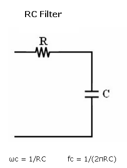
So, connecting joystick outputs to analog inputs of Xbee, select from joystick to digital input, configuring it as indicated in the link above, you will have the values at the receiver, in series 1 (802.15.4) you can get the values atthe receiver both through the UART (setting IU=1), and/or as PWM outputs. Depending on your purposes, you can use directly the PWM, but remember, is not "real" analog, you must use a RC filter to get the analog DC, also explained at digi.
In my case I recieved the API packet (line passing needs API mode), and get the values in my arduino/atmega328p code to process them and make the pirate4wd move according to joystick.
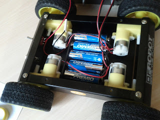
The car
The chasis used is the pirate4wd from dfrobot, mine came without manual, but it can be found online, although it is not really necessary, just to know the dc motor characteristics:
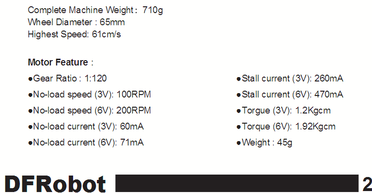
Seen the stall current perhaps a L298 is oversized, as it can source up to 2A per channel, but I just wanted to test this chip, I will have another try witrh L293 soon.
The controller is constructed at a pinhole board with atmega328p at 16Mhz, xbee socket for receiver mounted on Xbee Regulated board, 7805 5V regulator for atmega and L298 with its army of diodes (1N0007).

First thing is to solder motor cables, as L298 only has outputs for two motors, one solution is to connect each side motors to the same cable, but with polarity inverted, as they are oriented in opposite directions. Solder interruptor from batteries holder and then to a power output to the control board.
After mechanical part is solved, you have to deal with L298 control with atmega, you can find lot of tutorials online. If you don't already know, it is a good opportunity to learn about H brigde motor controllers. Knowing that, you just have to control motor direction with IN pins, and motor power level with ENABLE pins, using a PWM atmega output. I leave here my code.
Some tips that could be useful for other people trying to do something similar:
- socket for L298, as pins are separated 0.05 inch, you cannot connect it directly to a 0.1 inch hole board, it can be solved bending 45º the legs of a pin strip, solder that to the board and inserting L298 on it.
- separate power to motors and to microcontroller, I tried firstable powering 7805 5V output to atmega328p and regulator input to Vs pin of L298 (and output diodes supply) and I could see the current breakdown when driving the motor through a "power on" led connected an atmega digital ouput. After powering motors with a separate 9V supply, there is no influence from motors to microcontroller. Excellent explanation and video here.
- consider 9V min battery for motors. The AA batteries holder that comes with pirate4wd is 7.5V, and this is not too much for these dc motors. They will work, but not at 100% of their capacity. They run 100rpm at 3V and 200rpm at 6V, but. even with 7.5V you will have about 2.5V final voltage applied to motors. There is a important characteristic at L298 datasheet, it is the Source and Sink saturation voltage, that sums between 3.2V and 4.9V, so that leaves just (7.5 - 4.9) = 2.6V in the worst case for the motors.

- consider to program some "throttle smooth start control" in your atmega software, if you drive motor from 0 to 100 in 1 second then probably L298 will saturate (sure if you use less than 9V motor supply), you can see an example of gradual acceleration in my code defining a maximum acceleration per second "MAX_ACELERATION".
No hay comentarios:
Publicar un comentario