Mostrando entradas con la etiqueta uav. Mostrar todas las entradas

domingo, 20 de julio de 2014

CRIUS compass magnetic interference (compassmot)


The problem

I am using the CRIUS AIOP v2 flight controller, with MPNG 3.01 R3. I have been flying some months using auto modes without problems (loiter and auto missions). After a crash on a windy day I rebuilded the quad again using a H.A.L frame, as I am very pleased with the robustness and weight, and also price of it. This time I configured everything in the middle part to maintain the center of gravity as centered as possible, as my previous crash was produced messing around with different roll/pitch pid values trying to adapt to different weighted arms (camera and battery on one H.A.L arm).

With this new configuration, flying in auto missions some times at the time of changing from one waypoint to the next, in the momment of heading to face the next point the quad fails the angle and begin to fly in some random direction and I have to take manual control and bring it back home. This also happened in loiter, but just some times, it begins to lean one random angle and slowly fly away. I checked all the hardware parts without solving anything, in the end using compassmot I realized that I have a 65% of interference due to power cables, as this time the FC was about 1cm above the power cables, much closer than in any other configrations I did before.

Here a video of the effect at Loiter:


One solution

This was the original configuration, you can see the board  very close to the power cables (between thw two H.A.L. plater, near the orange plastic parts)
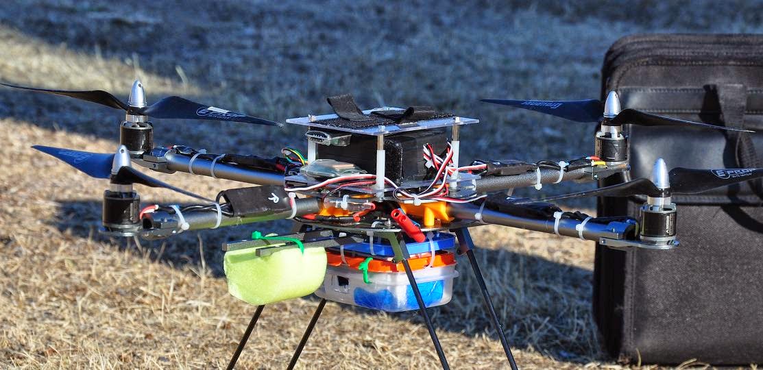
Hardware configuration with high magnetic interference

Detail of CRIUS FC position, 1cm above power cables
And the result of compassmot of 65%!!, using Attopilot current voltage and current sensor, properly configured in Mission Planner so in compassmot I was measuring current vs throttle:

65% Current vs Throttle interference

Here the new configuration, with the CRIUS FC 5cm above the power cables:

Hardware configuration with small magnetic interference

CRIUS FC board 5cm above power cables
The compassmot results shows a reduction to 10% interference, which results in a perfect loiter and auto mission performance. It is very important to do a new live compass calibration after moving the compass to other place, as offsets can vary significantly. I like also to do a live calibration periodically as recommended in the datasheet of the HMC5883L compass used in CRIUS, to take into account sensitivity drift due to temperature variations.

10% Current vs Throtle interference
If you cannot move away the FC then you can always use an external magnetometer I2C connected to the CRIUS board.

This is just one method to avoid magnetic interference, some others are described here, simple methods as twisting wires from battery to FC, and from FC to ESCs. For me this was the most effective as magnetic interference reduces with the cube of the distance to the source of the interference.


Magnetic interference

For a better understanding on how to solve one specific wiring ditribution on a quad it is good to understand a bit of the physics involved, simpliflying  the wire path from battery to flight board and then esc and return to battery as a circle (DC current, the one that produces most of the interference problem) :


The formula of magnetic field at a point at z axis, perpendicular to loop plane (Bz >> Bx, By, theoretically cancelled ina perfect loop), let us deduce some facts about how our wiring distribution would behave:


  •  the bigger the circcle the stronger the magnetic field (proportional to R)
  •  higher current implies higher interference (proportional to I)
  •  the field reduces as the cube of the distance to the source (1/z3 proportional)
  •  twisting the wires creates a sort of loop along the z plane (each twist one loop) that makes Bz somehow cancel itself along z axis, or at least been reduced.


domingo, 27 de abril de 2014

Balancing multirotor motors with MMA8452Q accelerometer


This post is about using the MMA8452Q acceleromter to balance multirotor motors. As there is alot of information in the net about the balancing procedure I am focusing on using this cheap accelerometer for that purpose.

The easier way would be to use some app in a 3g phone to get and idea of the vibrations at the motor, but I lost my phone a month ago and I was living happy without it and didn't wat to spend 300$ in a new one. So searching for cheap and easy to set up accelerometers, this is one of them: less than 10$, I2C interface, 12bit resolution and example code.


MMA8452Q hw & sw setup

The connections is quite straigth forward, just solder some wires and connect to and arduino for example. This is form the example code MMA8452Q_AdvancedExample at GitHub

 Hardware setup:
 MMA8452 Breakout ------------ Arduino
 3.3V --------------------- 3.3V
 SDA ----------------------- A4
 SCL ----------------------- A5
 INT2 ---------------------- D3
 INT1 ---------------------- D2
 GND ---------------------- GND

It is possible to interface directly from a 3.3V device to a 5V arduino because SDA&SCl pull-ups at Arduino are disabled . For this you must use the i2c.h file in the example instead of the standard Wire arduino library, that switch on the pull-ups (twi.c):
void twi_init(void)
{
  // initialize state
  twi_state = TWI_READY;
  twi_sendStop = true; // default value
  twi_inRepStart = false;

  // activate internal pullups for twi.
  digitalWrite(SDA, 1);
  digitalWrite(SCL, 1);

  // initialize twi prescaler and bit rate
  cbi(TWSR, TWPS0);
  cbi(TWSR, TWPS1);
  TWBR = ((F_CPU / TWI_FREQ) - 16) / 2;
  /* twi bit rate formula from atmega128 manual pg 204
  SCL Frequency = CPU Clock Frequency / (16 + (2 * TWBR))
  note: TWBR should be 10 or higher for master mode
  It is 72 for a 16mhz Wiring board with 100kHz TWI */
  // enable twi module, acks, and twi interrupt
  TWCR = _BV(TWEN) | _BV(TWIE) | _BV(TWEA);
}

The reason why this works is well explained in a comment in the product page at sparkfun, it is due to the open drain design of the i2c data lines. From sparkfun they notice that even without disabling the arduino pull-ups it works, and some users confirm it, because the final high voltage at the sensor input sda and scl lines would be 3.79V as a combination of sparkfun board 10k pull-ups to 3.3v and arduino 25k pull-ups to 5v, but I prefer to stay in the datasheet ranges, so I  disabled pull-ups at arduino.


I don't know why, but even reading in the sensor datasheet that a 4.7 ohms resistor is recommended as pull-up, sparkfun soldered 10k pull-ups in the board. Some users advice that seing signal at oscilloscope it appears quite rounded with 10k, and that it is better shaped with 4.7k, you can solder a paralell 10k to get 5k final resistante to pull-up, but I must say it works quite fine for me with the 10k resistors in the board.


Changing scale +/- 2g/4g/8g

It is neccesary to understand the Zero-g offset concept to understand the output values from the sensor. When stationary the output registers from the sensor will be 0x00 (ideally middle of dynamic range) , but in fact z g is 1g when laying flat and stationary. It is well explained in the application note AN4069.


At each scale each count from the ouput register means a different value of g. For example when the full-scale is set to 2g, the measurement range is -2g to +1.999g, and each count corresponds to 1g/1024
(1 mg) at 12-bits resolution, each count will mean double g value if scale is doubled to 4g, and same for 8g.

Then the value of counts stored in the offset registers are referred to a scale, and the value added to 0x00  output when flat and stationary to get 1g at z axis will only result in 1g when the scale is the same at which the calibration was done.

This can be confusing using the example code, if you change the default scale to 4g, you will get at flat and stationary : x=0g,y=0g and z=2g, and  x=0g,y=0g and z=4g when scale is 8g. You need to recalibrate if you want to see a pretty 1g for z, or if not at least understand what that value means.

Regarding scale also take into account that the scale is limited to 4g if you use the low noise mode, that is actiuvated by default in the example code


Using accelerometer data to balance multirotor motor

The procedure to balance a motor is well documented online, the idea is to place a weigth on different parts of the motor and compare the vibrations on each point. I did it using a ziptie and moving the head of the ziptie around the perimeter of the motor. In an ideal motor the vibrations woould be the same on every point, but in an unbalanced motor the vibrations will be less in the point where it is lighter.


You can plot the data in a easy way using Processing for example, that is what I tried first, but it is quite difficult to distinguish the difference in vibration level between two points simply observing the graphic. So I found it better to calculate mean value over time and comparing that mean at each point. That is an advantage of using arduino instead of a graphical phone application. If you sum up the mean on each axis you can get an idea of the overall vibrations generated by the motor. That all-axis mean cannot be used to compare vibrations between different motors unless you place the sensor equally leveled on all the motors, as z axis g value depends on the sensor horizontal level. But that all-axis mean can be used to compare vibrations in one motor placing the weigth at different points:


Summarizing the method:


  1. Place the sensor on one motor, measure mean gx,gy,gx (about 3000 samples) and calculate gx+gy+gz = overall_g
  2. Note values for (a) Motor alone (b) Ziptie at 4 positions separated 90 degrees
  3. Put some weigth ( tape for instance) on the position where overall_g was less using the ziptie
  4. Measure overall_g with the motor with that weigth and compare to value of motor alone in point 2, it should be less than alone.
  5. Add weigth on that point while the overall_g continues decreasing until it start to increase.

With this method I got between 0,2g and 0,6g less overall vibration placing tape at the motors. I did it with the motors attached to the multirotor and spinning one at a time.


domingo, 6 de abril de 2014

CRIUS AIOP v2 - Altitude hold based on MS5611 barometer


Some notes about the barometer included in the CRIUS AIOP flight controller and the importance of covering it with dark foam. I read some times about foam covering and I interpreted it as a way of getting more precise measurements, I expected to have some variance (cms, or 1, 2 meters as much)  if  you didn't cover it, but in fact it is absolutely necessary for being able to trust altitude measurements. Altitude is used in almost all common flight modes but Stailize and Acro (Auto, Altitude Hold, RTL, Loiter... )

The barometer used in CRIUS AIOP v2 is the MS5611-01BA03. This is an update from the MS5611-01BA01 used in previous versions of CRIUS board, but apart from the change from ceramic to metal case and slightly better response to variations in supply voltage, the specifications are same.


Having a quick look at the datasheet you see that the pressure calculated value depends on temperature, as the sensitivity of the sensor varies with it. Indeed there is a different calculation method for pressure when the temperature is below 20 degrees. This should not worry much if you fly in a cold day as long as the tempreature at the sensor remains more or less constant, but it would worry me if the temperature at the sensor suffers a dramatic change, say from 20 to 15 degrees in a very short time (due to a fresh air flow from the props for instance). It could easily led you from an altitude value of 10m to 500m, with the corresponding reaction from the copter....This kind of issue is what you can suffer if the sensor is exposed to sunlight or propwash.

I learned it by the hard way, the first flight with the sensor completely exposed gave me altitude values that varied as much as 500m from one momment to the other, just imagine the reactions from the multicopter when I was on any auto mode. 

In this log it can be seen the variations of 500m while trying to do a RTL (throttle in blue represent the reactions to such an altitude change, red is altitude, green is desired altitude)


So I covered the sensor with foam and introduced all the electronics into a dark box. I tried before just covering the sensor, but the altitude values were jumpy sometimes due to sunligth, for example one day I suffered a crash when the weather changed from foggy to shiny while copter was in the air. Conclusion: both air flow from propwash and sunligth produce important variations in temperature at the sensor, and in measured pressure therefore, so keep it calm and dark.


after that changes the values from the sensor were quite precise and now I can enjoy of rock solid loiters and auto missions. Here an example of the last log, you can't even distinguish the line of the desired altitude behind the real altitude:


And here a video demonstration of the perfect Loiter performance:


Quadcopter data:

- CRIUS AIOP v2
- MPNG 3.0.1 R2 firmware
- NTM 800kv 300W motors
- Graupner 12x6 props
- Rctimer 30A ESC with Simonk.


lunes, 13 de enero de 2014

Multicopter KK2.1 MPU6050 Settings


This post is about MPU6050 Gyro+Acceleromter settings on the Hobbyking KK2.1 Flight Controller board. The meaning of these settings didn't seem obvious to me, neither the effect on how to multicopter would fly with different values so I write this to help me and others to get a deeper understanding on it. These settings are available from the menu of the Steveis firmware version. Here you can get last version, mine is 1.11S1 (December 2013)


Full Scale Range

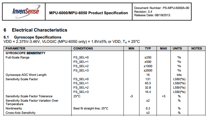
The values for Gyro(deg/sec) and Acc(+/-g) are the full scale range of each sensor. The MPU6050 can be configured with different scale ranges, individually for Gyroscopes and Accelerometers:


MPU6050 uses 16bit sigma-delta ADC for gyros and accs. Examining the values in the above tables we can know the minimun value that can be measured with each scale range, that is defined by the value of 1 bit (LSB) in sensor units.


So the conclusion of this is that for a bigger range we get a less accurate measurement, as the minimum value (Least Significant Bit) increases. For example, with a range of +-16g for the accelerometer we just can distinguish values of 0.49mg, while it is 0.06mg for a scale of +-2g.

For getting advantage of this knowledge we should know what are the values that occurs in a multicopter in the air, values produced by wind or by user input. Then we should set the minimum necessary range to cover our work values, so we have the best possible accuracy and also because of what is mentioned below.

I couldn't get any schematic of the internals of MPU6050, but I suppose that roughly it is something like this (taken from the Analog Devices AN-396 accelerometer),


Basically a pre amplifier followed by an amplifier which gain is what is modified to change the scale factor. So, as it is recommended in its datasheet, never use more gain than is needed to provide a convenient scale factor, as the buffer gain not only amplifies the signal but any noise or drift as well. So the ideal range will be the minor one while covering the range of deg/sec and g the multicopter will move.

I don't know yet acceleration values (g) or angles rate of change (deg/sec) that a multicopter is exposed. I depends of course on the type of flying you are doing (acro or smooth fpv).  I plan to take them from experimental values using the logging function on my CRIUS AIOP 2.0. One reference I have found is this from a technical article on context recognition, that could give an idea of acceleration of well known movements for us:


Low pass Filter


The MPU6050 has a user programmable low pass filter that affects equally to gyro and accelerometer. These are the possible frequency values:
  

In the end this value is used to filter unwanted deviations due to noise or vibrations affecting the multicopter, beacuse meaningful changes due to user input or wind are not supposed to have a frequency greater than 250Hz (1/250Hz = 4ms).

Just to help a little bit more, I leave this comment from the multiwii MPU6050_config.h config file, it is not a KK2.1 software but the information could be useful to understand the effects of LPF on multicopter behaviour:
/* MPU6050 Low pass filter setting. In case you cannot eliminate all vibrations to the Gyro, you can try
   to decrease the LPF frequency, only one step per try. As soon as twitching gone, stick with that setting.
   It will not help on feedback wobbles, so change only when copter is randomly twiching and all dampening    and balancing options ran out. Uncomment only one option!
   IMPORTANT! Change low pass filter setting changes PID behaviour, so retune your PID's after changing LPF.*/